How to Model Multiple Constraints in a SysML Constraint Block
Modeling Multiple Constraints in a Single SysML Constraint Block
Constraint blocks are one of the most powerful tools in SysML parametric modeling. They allow engineers to represent mathematical relationships between system parameters and simulate how values propagate through a system.
One common modeling question is:
Should constraints be modeled as separate constraint blocks, or grouped together within a single constraint block?
In this article, we explore how to model multiple constraints within a single SysML constraint block, when it makes sense to combine equations, and when it may be better to keep them separated.
We demonstrate these concepts using a simple but intuitive example: calculating the distance of a lightning strike based on the time between lightning and thunder.
Watch the full walkthrough here:
https://www.youtube.com/watch?v=js2f40KcyyM
The Example: Lightning and Thunder Distance Calculation
The classic rule for estimating lightning distance is based on the time delay between seeing lightning and hearing thunder.
Because light travels much faster than sound, the delay corresponds to how far away the strike occurred.
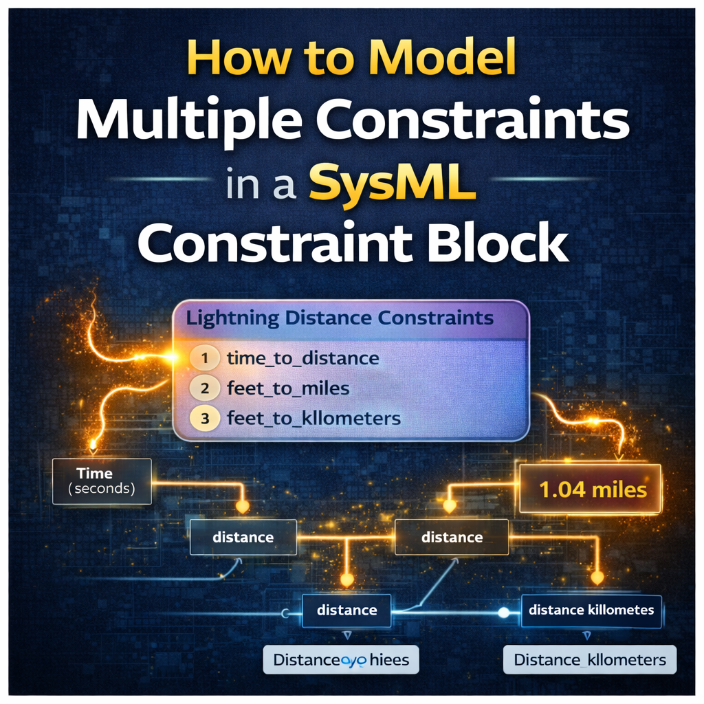
In our SysML model, we represent three equations:
1️⃣ Lightning Time to Distance
Converts time between lightning and thunder into distance in feet.
2️⃣ Feet to Miles Conversion
Converts the calculated distance in feet into miles.
3️⃣ Feet to Kilometers Conversion
Converts the calculated distance in feet into kilometers.
These equations are implemented using SysML constraint blocks and parametric diagrams.
Approach 1: Separate Constraint Blocks
The first modeling approach uses three individual constraint blocks.
Each equation exists as its own constraint block:
-
Time → Distance (feet)
-
Feet → Miles
-
Feet → Kilometers
In the parametric diagram, these constraint blocks are connected so that:
-
The input time value feeds the first constraint.
-
The output distance in feet becomes the input for the conversion constraints.
-
The final outputs are distance in miles and distance in kilometers.
This structure clearly shows how values propagate through the model.
Simulation Example
If we run the simulation with an input of 5 seconds, the model calculates:
Distance ≈ 1.04 miles
The parametric diagram automatically propagates this value through all constraints.
This approach works well when:
-
developing and testing equations
-
debugging models
-
validating constraint behavior individually
Approach 2: Multiple Constraints in One Constraint Block
The second approach places all three equations inside a single constraint block.
Instead of separate constraint blocks, the model contains one constraint block with three constraints defined within it.
This structure is visible in the containment tree, where the constraint block contains multiple equations.
The parametric diagram then uses only one constraint block usage, which internally evaluates all equations.
Despite the structural difference, the simulation produces the same result.
Running the model with a 5-second delay again yields:
Distance ≈ 1.04 miles
Both modeling approaches are mathematically identical.
The difference is purely in model structure and organization.
How to Add Multiple Constraints to a Constraint Block
Adding multiple constraints inside a single constraint block is straightforward in tools like Cameo Systems Modeler.
Steps:
1️⃣ Open the constraint block specification
2️⃣ Navigate to the Constraints section
3️⃣ Click Create to add a new constraint
4️⃣ Add additional equations as needed
Each equation can then reference parameters defined in the constraint block.
This allows several mathematical relationships to live within a single reusable modeling element.
When Should You Use Separate Constraint Blocks?
Separate constraint blocks are often useful during model development.
Advantages include:
-
easier debugging
-
clearer visibility of equation flow
-
easier validation of intermediate results
-
simpler parametric diagrams for learning or teaching
For early model development, separating constraints can make it easier to verify that each equation works correctly before integrating them.
When Should You Combine Constraints into One Block?
Combining constraints into a single block is often useful for final model organization.
Advantages include:
-
cleaner parametric diagrams
-
fewer constraint usages
-
better grouping of related equations
-
improved readability for complex systems
This approach is especially useful when several equations belong to the same domain or subsystem.
For example:
-
propulsion equations
-
guidance and control equations
-
electrical power calculations
-
thermal system equations
Grouping domain-specific equations within one constraint block keeps the model organized and easier to navigate.
Organizing Constraint Blocks by Domain
As system models grow more complex, organizing equations by domain becomes increasingly important.
For example, a complex system might contain constraint blocks such as:
-
Propulsion Constraints
-
Guidance and Control Constraints
-
Thermal Analysis Constraints
-
Power System Constraints
Each constraint block could contain several related equations.
This structure makes large SysML models far easier to understand and maintain.
Best Practice Workflow for SysML Constraint Modeling
A useful modeling workflow is:
Step 1: Develop Constraints Separately
Start by modeling each equation as an individual constraint block. This helps ensure that each equation works correctly.
Step 2: Validate with Simulation
Run parametric simulations to verify that values propagate correctly through the model.
Step 3: Consolidate Constraints
Once validated, combine related equations into shared constraint blocks.
This produces cleaner diagrams while preserving correct system behavior.
Key Takeaways
When modeling constraints in SysML:
• Constraint blocks define mathematical relationships between system parameters
• Multiple equations can exist within a single constraint block
• Separate constraint blocks are useful during model development
• Combined constraint blocks improve model organization
• Large systems benefit from grouping constraints by engineering domain
Both approaches are valid — the best choice depends on the complexity of the system and the purpose of the model.
Learn More SysML Modeling Techniques
If you are learning SysML parametric modeling, constraint blocks are one of the most important tools for representing system analysis.
Watch the full tutorial here:
https://www.youtube.com/watch?v=js2f40KcyyM
You’ll see a full walkthrough of how to build the constraint blocks, connect them in parametric diagrams, and run simulations.
Final Thoughts
Constraint blocks help bridge the gap between system architecture and engineering analysis.
By carefully structuring constraints and parametric diagrams, engineers can simulate system behavior, propagate values across subsystems, and validate design decisions early in the development process.
Understanding when to separate constraints versus combine them is a small modeling decision that can have a large impact on the clarity and maintainability of your SysML models.