What Is UML? How UML and SysML Work Together in Systems Engineering
What Is UML?
Understanding UML and Its Relationship to SysML
Unified Modeling Language (UML) is a standardized graphical modeling language used primarily in software engineering to visualize, design, and document software systems.
UML provides a consistent set of diagram types and symbols that allow engineers and developers to describe how software systems are structured and how they behave.
It represents a collection of industry best practices that have proven successful in modeling large and complex software systems.
UML diagrams are primarily graphical and help engineering teams:
-
visualize system architecture
-
communicate design ideas
-
explore alternative system designs
-
validate software architecture
Although UML is widely used in software engineering, it is not a development methodology itself. Instead, it is a modeling language that can be used alongside various software development processes.
What Is SysML?
SysML (Systems Modeling Language) is a graphical modeling language derived from UML but designed specifically for systems engineering rather than just software engineering.
While UML focuses primarily on software systems, SysML expands the modeling approach to represent complex systems that include multiple engineering disciplines.
These systems may include:
-
hardware
-
software
-
data and information flows
-
personnel and operations
-
procedures and facilities
SysML enables engineers to model the requirements, structure, behavior, and constraints of complex systems within a unified model.
Because of this capability, SysML has become the most widely used modeling language for Model-Based Systems Engineering (MBSE).
How UML and SysML Are Related
UML and SysML are closely related because SysML was originally derived from UML.
SysML is technically defined as a UML profile, meaning it extends and customizes UML to support systems engineering concepts.
Both modeling languages share many common characteristics:
-
graphical diagrams
-
standardized modeling notation
-
hierarchical modeling structures
-
visual representations of system behavior and architecture
However, SysML introduces additional modeling capabilities needed for systems engineering, including:
-
requirements modeling
-
parametric analysis
-
system-level architecture modeling
-
integration of hardware and software elements
In short:
UML → designed for software systems
SysML → designed for multidisciplinary systems
UML Diagram Types
UML diagrams fall into two major categories:
Structural Diagrams
These diagrams describe how system components are organized and related.
Examples include:
-
Class diagrams
-
Component diagrams
-
Object diagrams
-
Deployment diagrams
-
Package diagrams
Behavioral Diagrams
These diagrams represent how a system behaves and how elements interact.
Examples include:
-
Activity diagrams
-
Sequence diagrams
-
State machine diagrams
-
Use case diagrams
These diagrams help software engineers visualize how software components communicate and evolve over time.
SysML Diagram Types
SysML includes nine primary diagram types used for systems engineering.
They are typically grouped into three categories.
Behavioral Diagrams
-
Activity Diagram
-
Sequence Diagram
-
State Machine Diagram
-
Use Case Diagram
Structural Diagrams
-
Block Definition Diagram (BDD)
-
Internal Block Diagram (IBD)
-
Package Diagram
-
Parametric Diagram
Requirements Diagram
-
Requirements Diagram
These diagrams allow engineers to represent the structure, behavior, and requirements of complex systems within a single model.
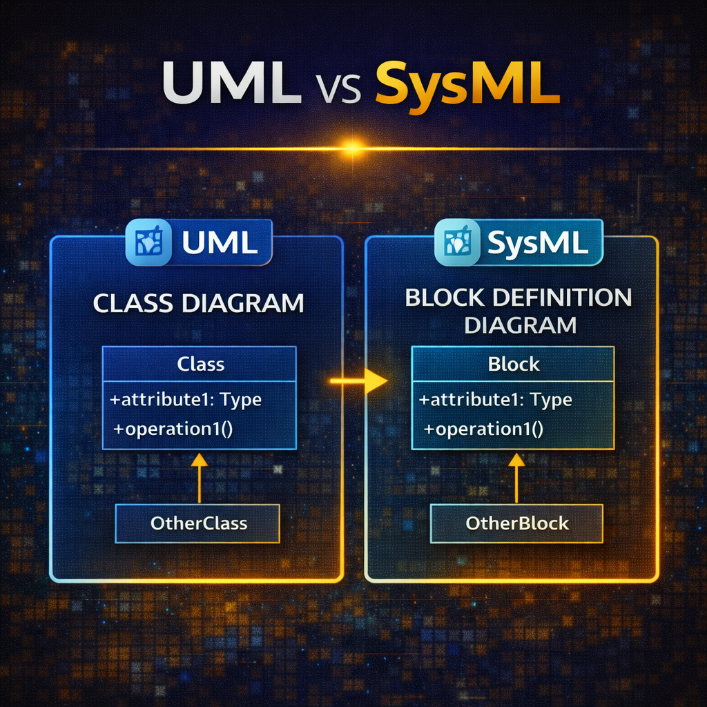
Mapping UML Diagrams to SysML Diagrams
Many SysML diagrams have direct counterparts in UML, allowing engineers to map concepts between software and systems engineering models.
For example:
| UML Diagram | SysML Equivalent |
|---|---|
| Class Diagram | Block Definition Diagram |
| Activity Diagram | Activity Diagram |
| Sequence Diagram | Sequence Diagram |
| Use Case Diagram | Use Case Diagram |
| State Machine Diagram | State Machine Diagram |
Although these diagrams share similar structures, SysML diagrams are adapted for system-level modeling, including hardware components, interfaces, and engineering constraints.
Visual Differences Between UML and SysML
When comparing UML and SysML diagrams, engineers will notice several subtle visual differences.
These differences often include:
-
different diagram icons
-
color schemes used by modeling tools
-
arrow styles and connector formatting
-
additional system-level elements in SysML
For example:
-
UML Class Diagrams correspond to SysML Block Definition Diagrams
-
SysML diagrams often include additional ports, flows, and requirement relationships
Despite these differences, the underlying modeling concepts remain very similar.
Creating UML and SysML Diagrams in Modeling Tools
In modeling tools such as Cameo Systems Modeler, engineers can easily create UML or SysML diagrams.
Typically this involves:
-
Selecting Create Diagram
-
Choosing UML diagrams or SysML diagrams
-
Selecting the specific diagram type
Many modeling tools visually distinguish the diagrams using different icons so engineers can quickly identify whether they are working with UML or SysML models.
Why Understanding UML and SysML Matters
Understanding both UML and SysML is important for engineers working across software and system domains.
UML is essential for software architecture and object-oriented design, while SysML enables engineers to model entire systems involving multiple engineering disciplines.
By understanding how these modeling languages relate and map to each other, engineering teams can:
-
communicate designs more effectively
-
integrate software and system architectures
-
manage complex system development projects
Final Thoughts
UML and SysML are two closely related modeling languages that play an important role in modern engineering.
UML provides powerful tools for modeling software systems, while SysML extends these concepts to support complex multidisciplinary systems used in Model-Based Systems Engineering.
Understanding how these languages relate helps engineers choose the right modeling approach when designing and analyzing complex systems.