SysML Structural Diagrams Explained: BDD, IBD, Parametric, and Package Diagrams
SysML Structural Diagrams Explained: BDD, IBD, Parametric, and Package Diagrams
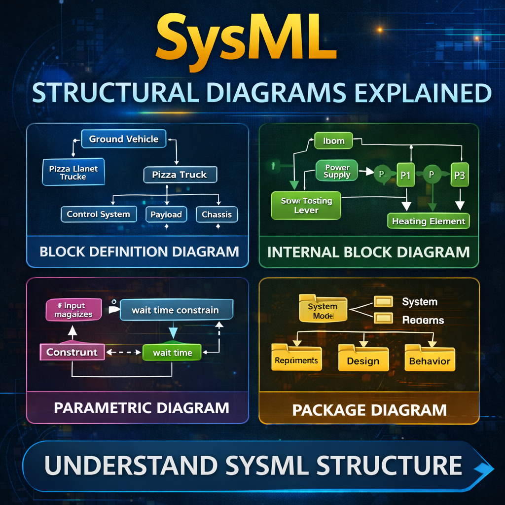
Structural diagrams are the foundation of system architecture modeling in SysML. They describe how a system is structured, how its components relate to one another, and how those components exchange information.
SysML provides four structural diagram types:
-
Block Definition Diagram (BDD)
-
Internal Block Diagram (IBD)
-
Parametric Diagram
-
Package Diagram
Understanding the role of each diagram helps systems engineers design clear, scalable models.
Watch the full explanation here:
https://www.youtube.com/watch?v=f5dgPvkBPJ4
Block Definition Diagram (BDD)
The Block Definition Diagram (BDD) is the most flexible structural diagram in SysML. It is primarily used for:
-
System decomposition
-
Taxonomy creation
-
Defining relationships between system elements
A BDD describes what components exist within a system and how they relate to each other.
For example, consider a Pizza Planet delivery truck system. A block definition diagram could show:
-
The Pizza Planet Truck is a type of Ground Vehicle
-
The vehicle contains several subsystems:
-
Control System
-
Payload
-
Chassis
-
Propulsion System
-
Two key relationships commonly appear in BDDs:
Generalization
Represents inheritance relationships (e.g., Truck is a type of Ground Vehicle).
Directed Composition
Represents whole-part relationships where a system contains subsystems.
Because it defines system structure at a high level, the BDD is typically the first structural diagram created in a SysML model.
Internal Block Diagram (IBD)
Once the system has been decomposed using a BDD, the next step is usually creating an Internal Block Diagram (IBD).
An IBD shows how the parts of a system connect and communicate with one another.
For example, imagine modeling a toaster. The internal block diagram might include components such as:
-
Power Supply
-
Start Toasting Lever
-
Heating Element
The IBD then shows:
-
Proxy ports representing interfaces
-
Connectors between parts
-
Item flows traveling between components
While the BDD defines what parts exist, the IBD explains how those parts interact inside the system.
Package Diagram
The Package Diagram focuses on model organization rather than system architecture.
In SysML tools like Cameo Systems Modeler, much of this structure is already visible through the containment tree. Because of this, package diagrams are not always required.
However, they can still be useful when:
-
Creating navigation pages for large models
-
Presenting model organization to stakeholders
-
Showing high-level architecture structure
Package diagrams are primarily used for managing the model itself rather than modeling the system of interest.
Parametric Diagram
The Parametric Diagram is a specialized type of internal block diagram used for engineering analysis and mathematical relationships.
Parametric diagrams connect value properties to constraint blocks, allowing engineers to represent equations and analytical relationships.
For example, imagine modeling a doctor’s waiting room system.
Inputs might include:
-
Number of magazines available in the waiting room
Outputs might include:
-
Average patient wait time
A constraint block can represent the mathematical relationship between these variables.
Parametric diagrams are commonly used for:
-
Mass roll-ups
-
Power budgets
-
Performance analysis
-
Engineering calculations
They allow the SysML model to support system-level analysis and simulation.
How These Structural Diagrams Work Together
A common modeling workflow looks like this:
-
Start with a Block Definition Diagram
-
Define the system and decompose it into subsystems.
-
-
Create Internal Block Diagrams
-
Show how those subsystems connect and exchange information.
-
-
Add Parametric Diagrams
-
Define engineering calculations and constraints.
-
-
Organize the Model with Package Diagrams
-
Structure the model for clarity and navigation.
-
This layered approach allows engineers to move from high-level architecture to detailed system analysis.
Key Takeaways
SysML structural diagrams serve different but complementary roles:
-
Block Definition Diagram (BDD) → Defines system components and relationships
-
Internal Block Diagram (IBD) → Shows how components connect and communicate
-
Parametric Diagram → Represents mathematical constraints and engineering analysis
-
Package Diagram → Organizes the model structure
For most systems engineering projects, the BDD and IBD form the backbone of the system architecture, while parametric diagrams enable analytical modeling.
As systems become more complex, mastering these diagrams becomes essential for building clear, scalable, and traceable system models.