How to Model Interfaces in SysML (Logical vs Physical Design)
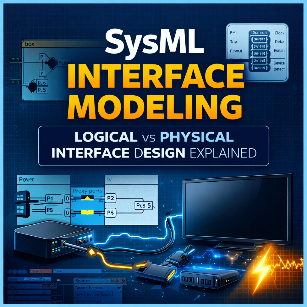
SysML Interface Modeling: Logical vs Physical Interface Design Explained
Interface modeling is one of the most important — and often misunderstood — aspects of SysML and Model-Based Systems Engineering (MBSE).
When engineers begin modeling system interfaces, a common question quickly appears:
What is the “correct” way to model interfaces in SysML?
The reality is that there is no single best method. SysML provides several valid modeling patterns depending on the level of abstraction, system maturity, and engineering needs.
In this article, we explore multiple approaches to SysML interface modeling, including logical interfaces, physical interfaces, connectors, proxy ports, and signal flows.
We will walk through a simple example — a box connected to a TV — and show how different modeling decisions affect the system architecture.
Watch the Full Interface Modeling Walkthrough
If you’d like to follow along in Cameo Systems Modeler, watch the full walkthrough below:
https://www.youtube.com/watch?v=pBYLmPnG_kY
This video demonstrates the complete interface modeling workflow step-by-step.
Why Interface Modeling Matters in SysML
In Model-Based Systems Engineering, interfaces define how subsystems interact.
Good interface models help teams:
• Define system architecture clearly
• Validate compatibility between components
• Reduce integration risk
• Improve traceability between subsystems
• Support digital engineering deliverables
Poorly defined interfaces are one of the leading causes of integration failures in complex systems.
SysML provides several modeling constructs to address this problem, including:
-
Internal Block Diagrams (IBDs)
-
Proxy Ports
-
Interface Blocks
-
Item Flows
-
Signals
-
Flow Properties
Understanding when and how to use these constructs is key to effective interface modeling.
Logical Interface Modeling in SysML
We begin with a logical system architecture.
Our system context is a simple Home TV Setup containing two subsystems:
-
Box
-
TV
These elements are connected within an Internal Block Diagram (IBD).
At the highest level, the system shows:
• Power supplied from an external source
• Data flowing from the box to the TV
At this stage, the model represents logical connectivity, not physical implementation.
Step 1: Define Signals
The first step is defining the types of information exchanged between components.
Typical examples include:
-
Data
-
Power
These signals are defined in a signal library and applied as item flows on connectors within the Internal Block Diagram.
This provides a simple representation of system interaction before introducing additional modeling structure.
Step 2: Add Proxy Ports
Next, we introduce proxy ports.
Instead of connecting directly to block properties, connectors attach to proxy ports placed on the subsystem boundaries.
Proxy ports represent the external interface surface of a component.
Benefits of proxy ports include:
• Clear interface definitions
• Improved modularity
• Easier interface reuse
• Better architecture clarity
Step 3: Type the Ports with Interface Blocks
Proxy ports are then typed using Interface Blocks.
For example:
| Interface Block | Purpose |
|---|---|
| Power Interface | Defines power flow |
| Data Interface | Defines data exchange |
Interface blocks define the set of flow properties available on the interface.
This creates a reusable and structured definition of subsystem interfaces.
Using Flow Properties for Interface Validation
Once interface blocks exist, we can add flow properties.
Flow properties define:
-
what flows through an interface
-
the direction of flow
For example:
+power : PowerSignal [in]
Modeling tools like Cameo Systems Modeler can automatically validate compatibility between connected interfaces.
If a connector attempts to pass an incorrect signal type, the model will flag a compatibility error.
This validation capability is one of the biggest advantages of formal interface modeling.
Modeling Detailed Data Signals
As systems mature, the model may need to represent more detailed data exchanges.
Instead of a single Data signal, we might represent:
-
Data
-
Control
-
Clock
-
Device Detection
-
Power
There are two common approaches.
Option 1: Multiple Signals
Each signal is modeled individually.
Example:
ClockSignal
ControlSignal
DetectDeviceSignal
Advantages:
• Explicit interface definition
• Easier traceability to specifications
Disadvantages:
• Diagrams can become cluttered
Option 2: One Signal with Multiple Attributes
Alternatively, a single signal can contain attributes representing multiple data types.
Example:
– clock
– control
– detect
Advantages:
• Cleaner diagrams
• Simpler models
Disadvantages:
• Less explicit signal representation
Both methods are valid SysML modeling approaches.
Physical Interface Modeling
After the logical architecture is defined, the model can evolve to include physical implementation details.
In our example system, the box connects to the TV using:
• HDMI cable
• Power cables
We also have physical connector information including:
-
HDMI Type A connector
-
Connector pinouts
-
Power connectors
At this stage, engineers must decide how much physical detail belongs in the SysML model.
Three Approaches to Modeling Physical Interfaces
The example demonstrates three valid modeling approaches.
Alternative A: Cables Not Modeled as Parts
In this approach:
• The box and TV remain the primary subsystems
• Cables are not modeled as part properties
Advantages:
-
Simpler model
-
Faster to build
-
Less diagram clutter
Disadvantages:
-
Less physical architecture detail
Alternative B: Cables Modeled as Part Properties
In this approach:
• HDMI and power cables become part properties in the system context.
Advantages:
-
Higher fidelity physical architecture
-
More explicit connectivity
Disadvantages:
-
Increased modeling effort
-
More complex diagrams
Alternative C: Association Block Modeling
A third option uses association blocks to represent cable relationships between components.
Association blocks can represent harness structures and intermediate elements connecting subsystems.
This approach is sometimes used when representing wiring harnesses or mechanical connections.
Connector-Level vs Pin-Level Modeling
Interface modeling can go to varying levels of detail.
Two common levels include:
Connector-Level Modeling
Represents connections between components using connectors.
Example:
Advantages:
-
Simpler
-
Faster modeling
-
Often sufficient for system architecture
Pin-Level Modeling
Models each individual pin in a connector.
Example:
HDMI Pin 2 → Signal B
Advantages:
-
Very high fidelity
-
Useful for electrical analysis
Disadvantages:
-
Extremely time-consuming
-
Large model complexity
A Critical MBSE Decision: When to Stop Modeling
One of the most important conversations for any MBSE team is:
How far down should we model the interface?
In many programs, the best solution is:
-
Model connectors in SysML
-
Reference electrical schematics for pinouts
This provides architecture visibility without unnecessary modeling overhead.
Using Detailed Views in SysML Models
A useful modeling strategy is separating:
• High-level architecture views
• Detailed interface views
For example:
-
A system-level diagram showing the box and TV connection
-
Detailed diagrams showing cable and connector breakdown
This allows different stakeholders to access the level of detail they need without overwhelming the architecture diagrams.
Signal Classification and Compatibility Checking
The example also demonstrates signal classification using generalization relationships.
Specific signals can be classified under a general signal type.
Example:
├── Clock
├── Control
├── DetectDevice
This allows connectors expecting Data signals to accept specialized signal types without compatibility errors.
Additional Interface Modeling Options
The example focuses on proxy ports, but SysML also allows other modeling constructs.
Possible alternatives include:
-
Full ports
-
Different interface abstraction patterns
-
Varying signal and item flow structures
Interface modeling approaches should always match the engineering objectives of the model.
Key Takeaways for SysML Interface Modeling
Effective SysML interface modeling should follow these principles:
Start simple
Begin with logical connectivity before introducing physical details.
Add detail only when necessary
More detail increases model complexity.
Align modeling depth with program needs
Not every interface requires pin-level modeling.
Use the model to validate architecture
Compatibility checks and structured interfaces are powerful tools for reducing integration risk.
Learn More About SysML and MBSE
If you’re interested in learning SysML modeling techniques used in real engineering programs, explore the resources below.
More tutorials and examples are available on the CameoMagic YouTube channel.
https://www.youtube.com/watch?v=pBYLmPnG_kY
SysML Interface Modeling: Final Thoughts
SysML provides powerful tools for defining system interfaces, but the flexibility of the language means engineers must make thoughtful modeling decisions.
The goal is not to capture every possible detail.
The goal is to build models that improve system understanding, reduce risk, and support engineering decisions.
By choosing the right level of abstraction, teams can use SysML to create clear, maintainable interface architectures.
Dear Cameomagic,
I hope this message finds you well. I am reaching out to inquire about your company’s current capacity availability, as we have an upcoming project slated to commence in the second half of the year. We would appreciate it if you could provide a quotation for your services to help us proceed with planning.
Looking forward to your feedback.
Best regards,
George Silver
Purchasing Manager
Nexans
George, we have reached out to you via email. To others who have consulting questions similar to this one, please reach out to us at consulting@cameomagic.com.
Dear Cameomagic,
I am reaching out to inquire about your company’s current capacity availability, as we have an upcoming project for which we’d like to request a quotation. We’d appreciate your feedback on feasibility and timelines.
Please let us know if you require any additional details to provide an estimate. We look forward to your response.
Best Regards
George silver
Nexans.com
George,
Thanks for your inquiry. We will email you shortly.
Hi, I’m Jay, we have a few potential clients that are interested in your services, thought you might be a good fit. I’d love to talk about the details, when do you have time to talk?
Best,
Jay
Founder | CEO