Language (SysML) & Tool (MagicDraw/Cameo) Guidance
Overview
SysML is a graphical modeling language used for capturing and expressing complex systems in a structured and organized manner. It is an important tool in the field of MBSE, as it helps modelers, engineers, and project managers to understand and communicate the complexity of systems effectively.
MagicDraw/Cameo is a popular modeling tool used by many organizations worldwide. It provides a range of features and tools to support the modeling and simulation of complex systems, making it an essential tool for many MBSE practitioners.
On this page, we will take you through the different types of SysML diagrams and explain when to use them. We will also explore the relationships between model elements, which are essential for understanding the behavior and structure of complex systems.
Whether you are a novice or an experienced practitioner, our guide will provide you with a wealth of information on SysML and the MagicDraw/Cameo tool. We will point you in the right direction for where to locate more information and provide you with tips and best practices for using these powerful tools effectively.
So, whether you are looking to brush up on your SysML knowledge or want to learn more about the MagicDraw/Cameo tool, our Language (SysML) & Tool (MagicDraw/Cameo) Guidance page is the perfect place to start.
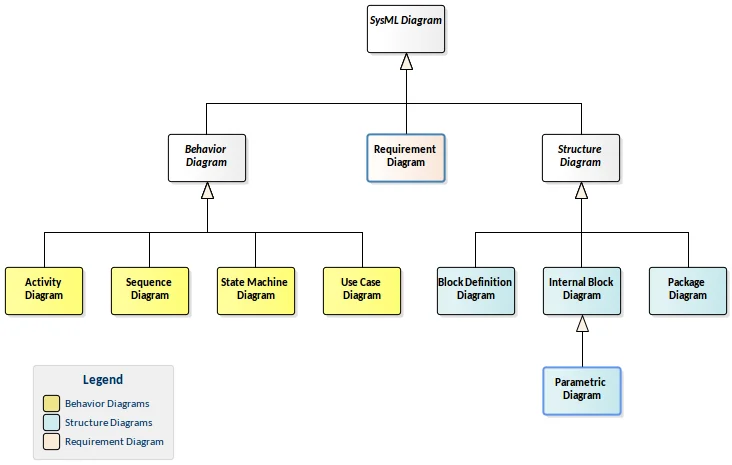
SysML Diagram Types
Structural Related
- Block Definition Diagrams (bdd)
- Internal Block Diagrams (ibd)
- Package Diagrams (pkg)
- Parametric Diagrams (par)
Behavioral Related
- Use Case Diagrams (uc)
- Activity Diagrams (act)
- State Machine Diagrams (stm)
- Sequence Diagrams (seq)
Requirement Related
- Requirements Diagrams (req)
SysML Diagrams Key Takeaway
The foundation of SysML is a set of nine diagram types, which are used to create a comprehensive system model. These diagram types are grouped into three main categories: Structural, Behavioral, and Requirement, each with their own unique set of elements. These elements are linked together to create a complete system model that captures the intricacies of a complex system.
Structural diagrams capture the physical and logical structure of a system, including its components, interfaces, and relationships. Behavioral diagrams capture the dynamic behavior of a system, including how it responds to various stimuli and events. Finally, Requirement diagrams capture the requirements that a system must fulfill, whether they are functional or non-functional.

For instance, the behavior of a system often takes place on a physical subsystem, and SysML allows us to connect the function or action with the physical component. Additionally, requirements imposed on the system can be structural, such as weight limitations, or functional, such as the system booting up within a specified time frame. These requirements can be captured using various SysML elements such as value properties or durations from Sequence diagrams.
With SysML’s comprehensive set of diagram types and elements, it is possible to create a detailed and accurate system model that captures all aspects of a complex system. For more information on SysML key concepts, please refer to our additional resources page.
One special type of diagram is the Parametric diagram, which is a powerful tool for analyzing and optimizing the system’s behavior. It is technically a subset of Internal Block diagrams, but due to its unique capabilities, it is often treated separately during instruction.