SysML Behavioral Diagrams Explained: Activity, Sequence, State Machine, and Use Case
SysML Behavioral Diagrams Explained: Activity, Sequence, State Machine, and Use Case
Behavioral modeling is a core part of Model-Based Systems Engineering (MBSE). While structural diagrams describe what a system is made of, behavioral diagrams describe how the system operates.
SysML provides several behavioral diagram types, each designed for a specific purpose. Choosing the correct one helps engineers clearly communicate workflows, interactions, system states, and system goals.
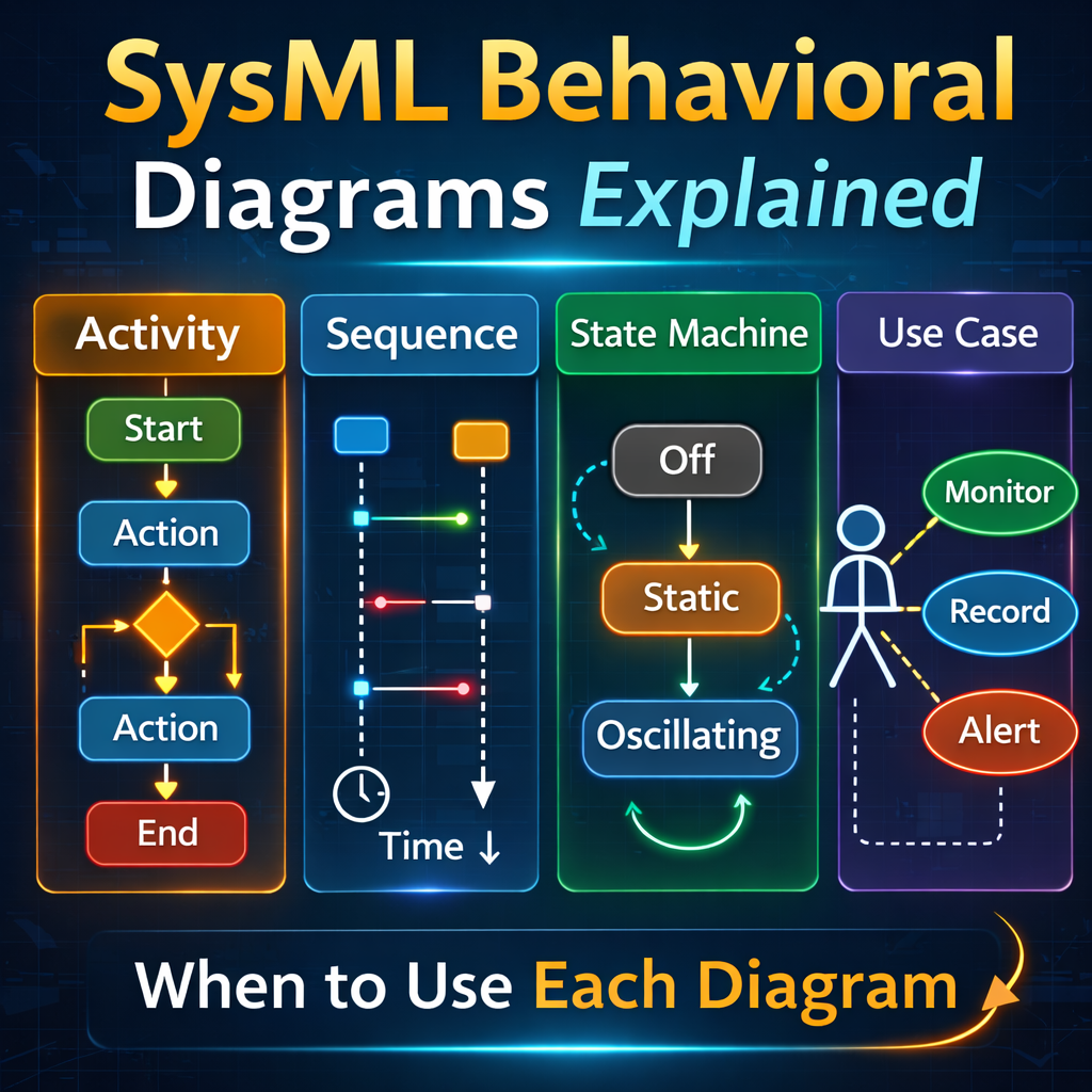
In this guide we explain four key SysML behavioral diagrams:
-
Activity Diagrams
-
Sequence Diagrams
-
State Machine Diagrams
-
Use Case Diagrams
We will also discuss when each diagram should be used during the system lifecycle.
Watch the full explanation here:
https://www.youtube.com/watch?v=2Y–p4yNKjk
Activity Diagrams
The activity diagram is one of the most flexible behavioral diagrams in SysML.
Activity diagrams represent workflows and logical flows of actions within a system. They show how activities move from one step to another using control flows and decision logic.
Typical elements in an activity diagram include:
-
activities and actions
-
control flows
-
decision nodes
-
merges
-
forks and joins
Because of their flexibility, activity diagrams are commonly used to model:
-
operational workflows
-
system processes
-
algorithm logic
-
subsystem behaviors
If you are unsure which behavioral diagram to use, activity diagrams are often the best starting point.
Sequence Diagrams
A sequence diagram focuses on interactions between system components over time.
The diagram is organized with lifelines across the top, and time progresses downward on the page. Messages are sent between lifelines to represent communication or interactions.
Sequence diagrams are particularly useful when modeling:
-
communication protocols
-
message passing between subsystems
-
command and response behavior
-
timing requirements
Constraints can also be added to represent timing requirements. For example:
-
a message must arrive within 20 minutes
-
a response must occur within 2 hours
Because time progression is explicit in sequence diagrams, they are ideal for time-dependent scenarios.
State Machine Diagrams
A state machine diagram describes how a system transitions between different states.
Each state represents a mode of operation, and transitions define the triggers that cause the system to move from one state to another.
For example, an oscillating fan might have states such as:
-
Off
-
Static
-
Oscillating
Transitions occur when events happen, such as a user pressing a button.
State machines are often used for high-level system control. They can also call lower-level behaviors such as activity diagrams.
For instance, when the system transitions into a specific state, an activity diagram may be executed as an entry behavior.
Because of this, state machines often act as a central coordination diagram for the behavior of the entire system.
Use Case Diagrams
A use case diagram is typically created during the early design phase of a project.
Its primary purpose is to capture what the system is expected to do from the user perspective.
Use case diagrams identify:
-
system actors
-
user interactions
-
system goals
For example, if the system of interest is a surveillance system, use cases might include:
-
monitor environment
-
record video
-
alert operator
Use case diagrams help define system scope and requirements before detailed modeling begins.
Once the system design progresses beyond the early phases, use case diagrams become less central to the modeling effort.
Choosing the Right Behavioral Diagram
Each behavioral diagram type serves a different purpose.
Activity Diagrams
Best for modeling process flows and system behavior.
Sequence Diagrams
Best for modeling interactions and timing between system components.
State Machine Diagrams
Best for modeling system modes and high-level control logic.
Use Case Diagrams
Best for defining system functionality during early project phases.
Key Takeaways
Understanding when to use each behavioral diagram helps engineers create clearer and more effective system models.
-
Activity diagrams are the most flexible behavioral diagram.
-
Sequence diagrams are ideal for time-dependent interactions.
-
State machine diagrams coordinate system-level behavior.
-
Use case diagrams define system goals during early design phases.
Selecting the correct diagram allows systems engineers to communicate system behavior more clearly and build more effective SysML models.