Modeling Process Guidance
Overview
The Roadmap
First, you will need to identify the scope of the project. Establishing the scope of the project will help you to determine the design goals and objectives for the project. You should also take into consideration any external factors that may affect the design process, such as the available budget and timeline. Once you have identified the project scope and goals, you should then begin to develop an architecture & design plan. This plan should include the design objectives, the design process, the design deliverables, and the timeline. It should also include a list of stakeholders and their respective roles. Next, you should conduct a requirements analysis. This analysis should include a detailed review of the existing system, the current architecture & design, and the user requirements. This analysis should also include a review of any applicable standards and regulations, as well as a review of any new technologies that may be needed for the project. The design process should then be conducted. This will involve the development of a high-level architecture .
Phase I: Creating the Backbone
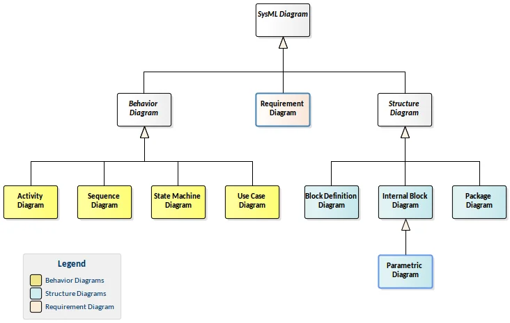
How to Drive: SysML Low Level Guidance
This page will provide an in-depth description of every aspect of each diagram, outlining the purpose and use of each element. It will also provide detailed examples of how to use each diagram, including best practices and tips for getting the most out of them. Finally, it will provide links to helpful resources and references that can be used to further study and understand the diagrams. By providing this comprehensive explanation and guidance, the page will help those working with SysML diagrams to understand the low-level details and how to use the diagrams to their fullest potential.
This guidance provides the fundamentals which is analogous to learning how to drive the car. Learning the language, the tool, and the methodology will help you understand where the peddles are, how to steer, & how to navigate the traffic laws.
Phase II: Adding System Specific Content
Turn by Turn Directions:
Implementing A Design Process
This page will help guide you through the steps to develop a model from scratch to “catch up” to the lifecycle stage in which the system-of-interest is currently in.
We estimate each of these phases to take 4 systems engineers 4 months complete. This can be scaled to fit a tighter timeline if necessary. This assumes the system-of-interest is just starting the production phase of the system lifecycle.
This guidance is a process which is analogous to turn by turn directions from your starting point to your destination.

Phase III: Solving Problems & Success Stories
Staying on the Road: Best Design Practices
This page will provide a comprehensive list of best design practices and tips and tricks to help you create the best product possible.
This guidance is various abstract topics/tips which will help you stay on the road during the journey. As everyone knows, if you fall off the road, you will hit bumps which will slow you down. While off the road, you can potentially get lost from the roadmap you were initially following and really struggle to find your destination.

Prerequisites
The documentation below will allow a smaller company or one which has little experience with MBSE to hit the ground running and produce a product good enough to demo to a customer. In an ideal situation, your company would have the Digital Engineering Environment (DEE) setup at the beginning of the effort with all of the software tools connected, licenses working, and threads completed. Read more about the DEE, different tools and threads available here: Tool Classes in the DEE & What is a Digital Thread.
If you are a large company with a DEE setup team then you get quite the head start as these threads will be prebuilt for you. It’s strongly advised that you use the threads provided in your setup even though it may seem more complicated at first. If you don’t there will likely be rework later. Put emphasis on adhering to a methodology and training your team in that methodology so that all modelers are on the same page and working the same direction.
Environment Setup
Model With A Purpose
Methodology
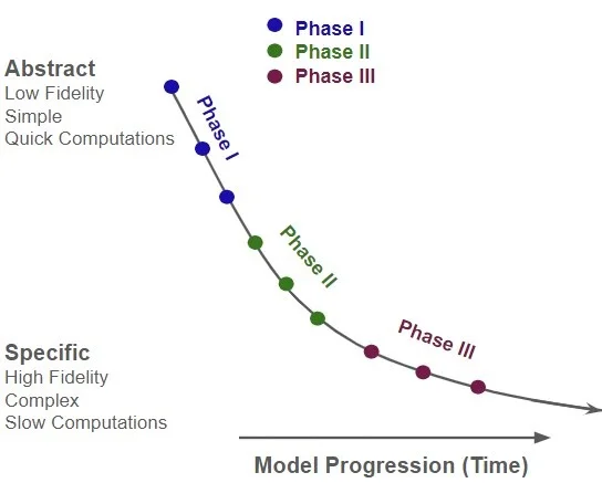
Model Progression Graph
High Level Phase Intent and Measures of Success

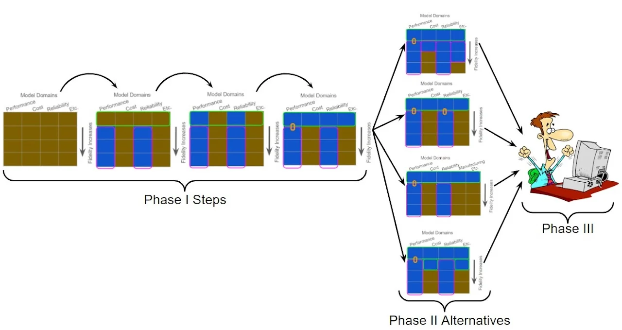
Model Development in Each Phase
The blue blocks refer to the amount of depth added to the model (how deep the water is) while the brown blocks refer to levels of fidelity which have not yet been built out (the rocks at the bottom). These will be explained in much greater detail in the Phase I and Phase II pages.
The main takeaway is that model creation is an agile approach which starts fairly structured, but then allows for more development alternatives, creativity, and freedom as the model is built out.
Further Explaining the Matrix Above
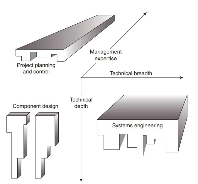
The figure below shows another aspect, the management expertise, as a third dimension. The figure shows how systems engineers fit into the team along with the project managers and the technical experts/design specialists.
Cameo is a systems engineering tool which allows systems engineers to thread to specialist’s simulations and allow a model with technical depth and breadth. The orange link represents a thread which is joins the two puzzle pieces: 1) the “systems engineering” elements and 2) the “component design” elements.
Read Model Based Systems Architecture, pg32 for more details.
Model Progression Graph Detail
- Determine Project Scope: What is the system, what is the system of systems, what are the subsystems
- Initial Vision: Determine Model Domains Desired and Priority (Stakeholder Interaction Map)
- Basic Framework: Buildout Abstract Top Level Assembly bdd
- Threads Buildout: Add value property “hooks” to where threads will connect. Investigate threading details
- Report Generation: Create VTL Scripts
- Manually Added Content & 1st Order Equations
- Focus On End User Usability: Meta Model Data & Navigation Page
- Probe End User for Tasks Model Could Solve
- Add Content & Cleanup to solve End User’s Problem

Note: When steps happen in parallel they are labelled on the same reference point in the diagram.